In this section I’ll build 4 mini-projects to learn how HAL (Hardware Abstraction Layer) and the GPIO (General Purpose Input/Output) of the STM32 board Nucleo F030R8. The manual for this board can be found at this link. The code can be found at my public repository for my STM32 projects, the code will still be provided in this section. The code is written in C, on STM32CubeIDE, and can be copied and pasted in the main.c (or any other file) and be used freely.
Project 1 – Blinking LED
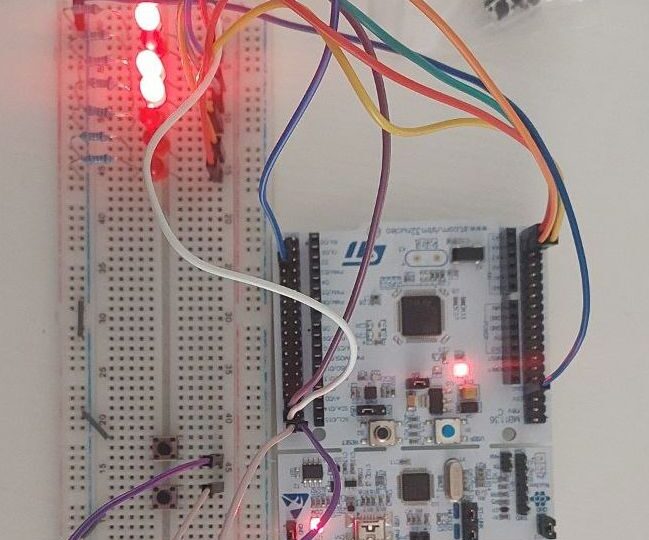
To start off, I’ve build a simple on/off automatic switch that justs turns on and off a LED. The circuit is made of a LED, a 220 ohm resistor ans some jumpers.
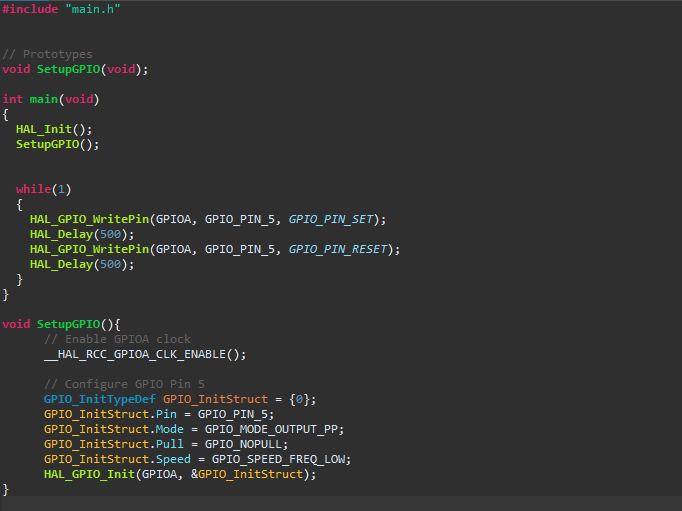
The code is simple, set the GPIO Port A, PIN 5 to output mode, no pull resistors, initialize HAL for the board and in the main() function set the set and reset for the GPIO_PIN_5. The code is give below:
Project 2 – Alternating Blinking LED
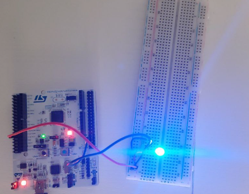
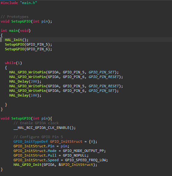
A slight modification of Project 1, this time whenever the 1st LED is on, the second is off and after a set delay they will be toggled (1 to 0 or viceversa). Since there is a second PIN, this one has to be set as output mode too, same settings as the first LED. We can see the SetupGPIO() function is starting to be useful so I’ve changed it to get a unsigned 16 bit integer as an argument. Code is given below:
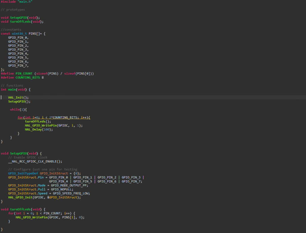
Project 3 – 8bit Shift Register
Now that I’ve learnt how output mode PINs work, let’s step up a bit and build an 8bit Shift Register.
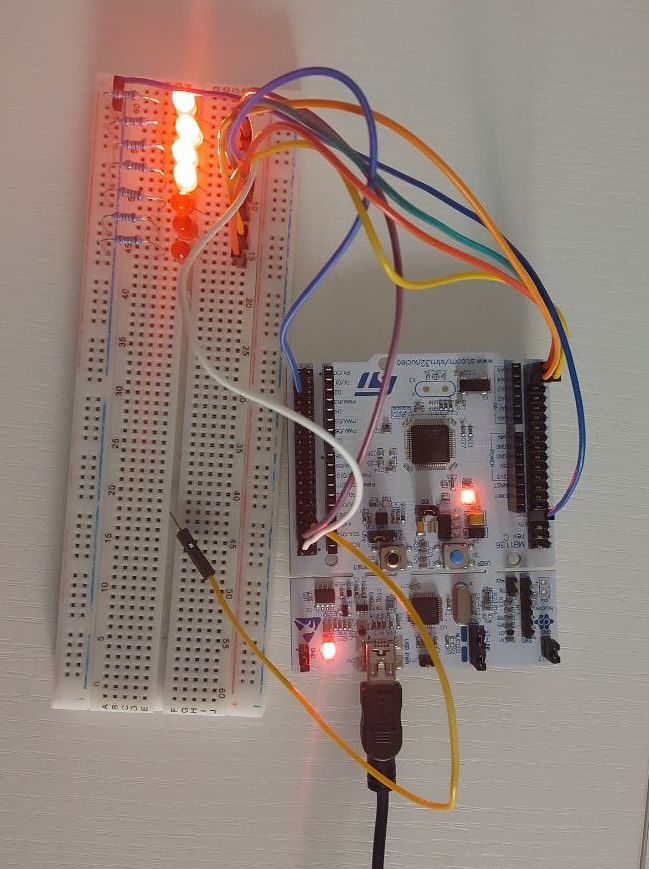
While it might seem a simple project, a shift regiter is widelly used not only as a sequential register, but it’s also a clock divider (each PIN divides the Delay time by 2), or an 8 bit counter (2^8 = 256). This time using the SetupGPIO() function needs to be called 8 times so i’ve gathered the 8 pins into an array. The code below doesn’t include the said loop because i was testing. Let’s say this is not optimal and should not be considered as base untill the SetupGPIO() function is not included for the code illustration below:
The code counts up to a constant COUNTING_BITS, the highest number is 8 but a 2 complement count can be implemented too maybe changing the LED color aswell).
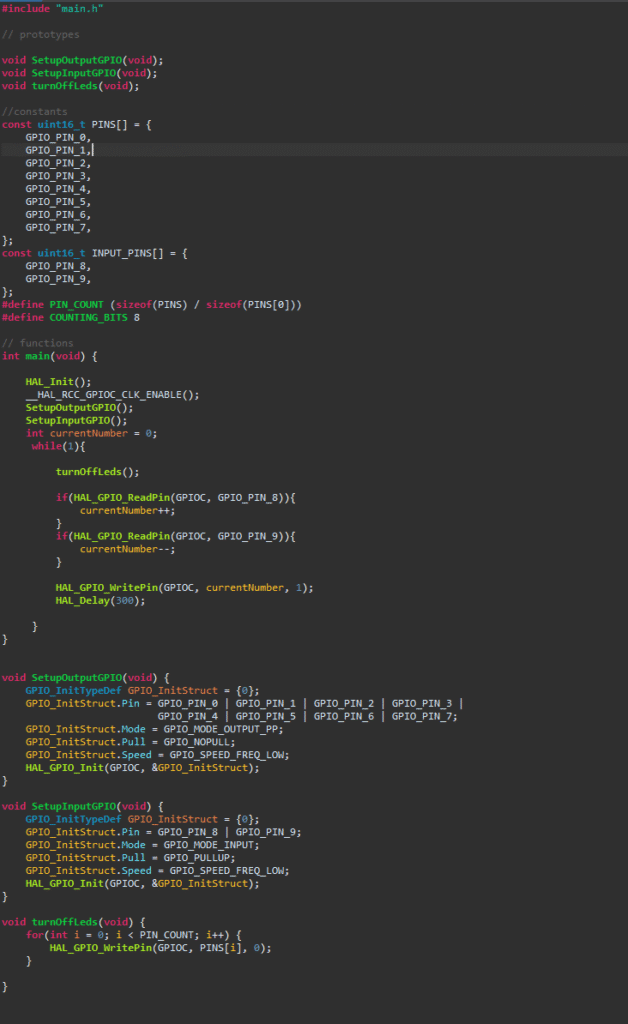
Project 4 – Manual Shift Register
As last mini project I’ll set 2 pins in Input mode with pullup resistors (which connect said pins to the logic 1 / 5V throught a resistor) use two buttons to connect the input to GND when pressed. The buttons’s functions add or remove an 1 from the current number.
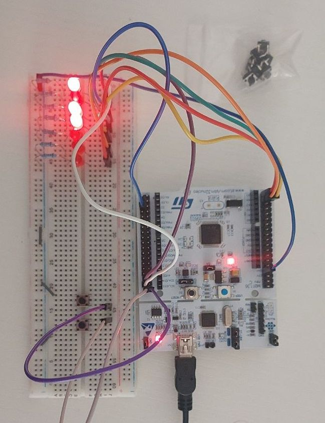
The code is similar to the 3rd project, with a small adjustment and a rename (SetupGPIO() became SetupOutputGPIO()). Same as before, it would be optimal to implement the function to be called inside a loop to activate every PIN automatically.
Conclusion
I’ve learnt the basics of GPIO and HAL usage for STM32 Nucleo – F030R8 and i can now implement sensors for temperature, humidity, light etc…